RDI ADCP Time Series
Data files for Teledyne RDI ADCPs are described here. Ancillary data (e.g., temperature, pitch, roll) are also available independently, through scalar data products, see time series scalar data and time series scalar plots.
Revision History
- 20141222: Heading correction rework (affecting ENU / uvw velocities): handle sites with null positions, mobile sensors, autonomous deployments, and better documentation of processing was done to the data.
- 20130317: Bug fixes, including making the number of dimensions of data structures fixed (trailing singleton dimensions are always dropped in MATLAB however).
- 20110328: NetCDF, CF1.5 compliant product released.
- 20110202: Correction for determination of ENU (with respect to true North) velocities. Prior code assumed ADCP was downward-facing. Updated code uses orientation or instrument to convert to ENU coordinates.
- 20100521: Derived backscatter added to MAT contents.
- 20100513: Initial NetCDF product released for RDI ADCPs, available in CF-1.4 compliant format.
- 20100218: MAT contents made more complete and descriptive
- 20091208: Initial PRF and MAT products released
Formats
This data is available in RDI, MAT and NETCDF formats. Content descriptions and example files are provided below.
RDI
This binary format is specific to the manufacturer. When using Teledyne-RDI data acquisition software, data is normally stored in this way. Although we use custom-built drivers to communicate with our instruments, we can use the raw data in the log file to produce the RDI file which can be interpreted by Teledyne-RDI post-processing software.
To produce the file, the following requirements apply:
- A new RDI file is started at the beginning of each day, when the maximum records per file is exceeded, or when the driver is restarted (this should account for configuration changes, site changes, etc).
- Only records with valid checksums are included.
- The instrument date/time field is replaced using the NEPTUNE timestamp at the beginning of the log file (since this timestamp is more accurate than the instrument clock), and the checksum is recalculated.
- Heading data is provided by the on-board compass, which is often unreliable due to interference. Users may correct this manually in the post-processing software with known good headings. These headings may be found in the meta-data reports that accompany most data search results or in the site tab found on the device details page (links found in step 2 of data search, for example: http://dmas.uvic.ca/DeviceListing?DeviceId=20003)
This format is further described in the manufacturer's documentation.
Example: RDIADCP75WH3808_20101106T000225.rdi
Note: This data product could be misleading as the heading corrections have not been applied; therefore, it is only available through direct request. When we are able to produce heading-corrected RDI files, we will again offer this data product.
MAT
MAT files (v7) can be opened using MathWorks MATLAB 7.0 or later. The file contains four structures: meta, adcp, config, and units.

- deviceID: A unique identifier to represent the instrument within the Ocean Networks Canada data management and archiving system.
- creationDate:Date and time (using ISO8601 format) that the data product was produced. This is a valuable indicator for comparing to other revisions of the same data product.
- deviceName: A name given to the instrument.
- deviceCode: A unique string for the instrument which is used to generate data product filenames.
- deviceCategory: Device category to list under data search ('Echosounder').
- deviceCategoryCode: Code representing the device category. Used for accessing webservices, as described here: API / webservice documentation (log in to see this link).
- lat: Fixed value obtained at time of deployment. Will be NaN if mobile or if both site latitude and device offset are null. If mobile, sensor information will be available in mobilePositionSensor structure..
- lon: Fixed value obtained at time of deployment. Will be NaN if mobile or if both site longitude and device offset are null. If mobile, sensor information will be available in mobilePositionSensor structure.
- depth: Fixed value obtained at time of deployment. Will be NaN if mobile or if both site depth and device offset are null. If mobile, sensor information will be available in mobilePositionSensor structure.
- deviceHeading: Fixed value obtained at time of deployment. Will be NaN if mobile or if both site heading and device offset are null. If mobile, sensor information will be available in mobilePositionSensor structure.
- devicePitch: Fixed value obtained at time of deployment. Will be NaN if mobile or if both site pitch and device offset are null. If mobile, sensor information will be available in mobilePositionSensor structure.
- deviceRoll: Fixed value obtained at time of deployment. Will be NaN if mobile or if both site roll and device offset are null. If mobile, sensor information will be available in mobilePositionSensor structure.
- siteName: Name corresponding to its latitude, longitude, depth position.
- locationName: The node of the Ocean Networks Canada observatory. Each location contains many sites.
- stationCode: Code representing the station or site. Used for accessing webservices, as described here: API / webservice documentation (log in to see this link).
- dataQualityComments: In some cases, there are particular quality-related issues that are mentioned here.
- MobilePositionSensor: A structure with information about sensors that provide additional scalar data on positioning and attitude (latitude, longitidue, depth below sea surface, heading, pitch, yaw, etc).
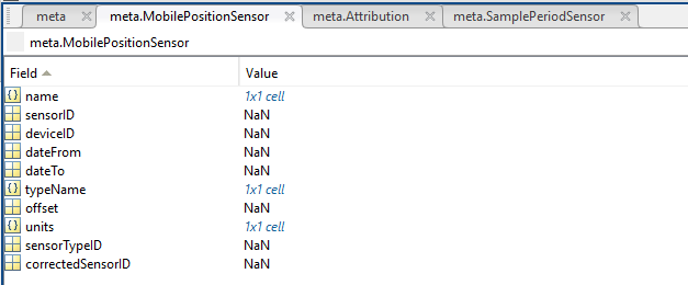
- name: A cell array of sensor names for mobile position sensors. If not a mobile device, this will be an empty cell string.
- sensorID: An array of unique identifiers of sensors that provide position data for mobile devices - this data may be used in this data product.
- deviceID: An array of unique identifiers of devices that provide position data for mobile devices - this data may be used in this data product.
- dateFrom: An array of datenums denoting the range of applicability of each mobile position sensor - this data may be used in this data product.
- dateTo: An array of datenums denoting the range of applicability of each mobile position sensor - this data may be used in this data product.
- typeName: A cell array of sensor names for mobile position sensors. If not a mobile device, this will be an empty cell string. One of: Latitude, Longitude, Depth, COMPASS_SENSOR, Pitch, Roll.
- offset: An array of offsets between the mobile position sensors' values and the position of the device (for instance, if cabled profiler has a depth sensor that is 1.2 m above the device, the offset will be -1.2m).
- sensorTypeID: An array of unique identifiers for the sensor type.
- correctedSensorID: An array of unique identifiers of sensors that provide corrected mobile positioning data. This is generally used for profiling deployments where the latency is corrected for: CTD casts primarily.
- deploymentDateFrom: The date of the deployment on which the data was acquired.
- deploymentDateTo: The date of the end of the deployment on which the data was acquired (will be NaN if still deployed).
- samplingPeriod: Sample period / data rating of the device in seconds, this is the sample period that controls the polling or reporting rate of the device (some parsed scalar sensors may report faster, some devices report in bursts) (may be omitted for some data products).
- samplingPeriodDateFrom: matlab datenum of the start of the corresponding sample period (may be omitted for some data products).
- samplingPeriodDateTo: matlab datenum of the end of the corresponding sample period (may be omitted for some data products).
- sampleSize: the number of readings per sample period, normally 1, except for instruments that report in bursts. Will be zero for intermittent devices (may be omitted for some data products).
- SamplePeriodSensor: A structure array with an entry for each scalar sensor on the device (even though this metadata is for complex data products that don't use scalar sensors).
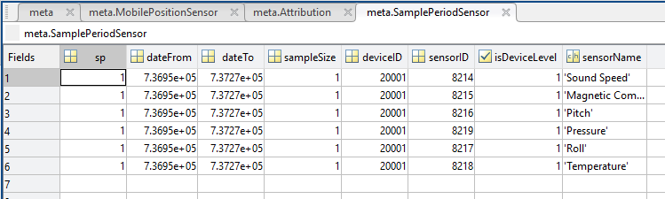
- sp: sample period in seconds (array), unless sensorid is NaN then this is the device sample period
- dateFrom: array of date from / start date (inclusive) for each sample period in MATLAB datenum format.
- dateTo: array of date to / end date (exclusive) for each sample period in MATLAB datenum format.
- sampleSize: the number of readings per sample period (array). Normally 1, except for instruments that report in bursts. Will be zero for intermittent devices.
- deviceID: array of unique identifiers of devices (should all be the same).
- sensorID: array of unique identifiers of sensors on this device.
- isDeviceLevel: flag (logical) that indicates, when true or 1, if the corresponding sample period/size is from the device-level information (i.e. applies to all sensors and the device driver's poll rate).
- sensorName: the name of the sensor for which the sample period/size applies (much more user friendly than a sensorID).
- citation: a char array containing the DOI citation text as it appears on the Dataset Landing Page. The citation text is formatted as follows: <Author(s) in alphabetical order>. <Publication Year>. <Title, consisting of Location Name (from searchTreeNodeName or siteName in ONC database) Deployed <Deployment Date (sitedevicedatefrom in ONC database)>. <Repository>. <Persistent Identifier, which is either a DOI URL or the queryPID (search_dtlid in ONC database)>. Accessed Date <query creation date (search.datecreated in ONC database)>
- Attribution: A structure array with information on any contributors, ordered by importance and date. If an organization has more than one role it will be collated. If there are gaps in the date ranges, they are filled in with the default Ocean Networks Canada citation. If the "Attribution Required?" field is set to "No" on the Network Console then the citation will not appear. Here are the fields:

- acknowledgement: the acknowledgement text, usually formatted as "<organizationName> (<organizationRole>)", except for when there are no attributions and the default is used (as shown above).
- startDate: datenum format
- endDate: datenum format
- organizationName
- organizationRole: comma separated list of roles
- roleComment: primarily for internal use, usually used to reference relevant parts of the data agreement (may not appear)
adcp: structure containing the ADCP data, having the following fields.
- range: vector of distance to each bin
- corr: 3D matrix, correlation time-series for each bin
- intens: 3D matrix, intensity time-series for each bin (also known as received signal strength intensity or RSSI)
- velocity: 3D matrix, corresponds directly to output of instrument and so depends on configuration coordinate system
- percentGood: 3D matrix, percent good time-series for each bin
- ens: vector, ensemble number
- compassHeading: vector, magnetic compass heading time-series
- pitch: vector, pitch time-series
- roll: vector, roll time-series
- time: vector, timestamp in datenum format (obtained from time the reading reached the shore station)
- temperature: vector, temperature time-series
- salinity: vector salinity time-series, (may contain constant values depending on device configuration)
- pressure: vector, pressure time-series
- depth: vector, depth of the device as measured by the device for each ping. This will vary with the tide and more so if the device is mobile. It should be consistent with meta.depth.
- soundSpeed: vector speed of sound time-series, (may contain constant values depending on device configuration)
- uMagnetic (optional): 2D matrix, East velocity relative to magnetic North
- vMagnetic (optional): 2D matrix, North velocity relative to magnetic North
- processingCommments: a string documenting all of the processing steps done to produce adcp.u/v/w
- velocity_sourceInfo: a string describing the source of data in adcp.velocity
- uvw_sourceInfo: a string describing the resulting final, rotated data in adcp.u/v/w
- u: 2D matrix, East velocity relative to True North
- v: 2D matrix, North velocity relative to True North
- w: 2D matrix, Upward Velocity
- velocityError: 2D matrix, computed using RDI algorithm
- backscatter: 3D matrix based on received signal strength intensity (adcp.intensity), compensated for two-way spreading (20LogR) and absorption. Equation based on Gostiaux and van Haren ("Extracting Meaningful Information from Uncalibrated Backscattered Echo Intensity Data, Journal of Atomsheric and Oceanic Technology, 72, 943-949, 2010). The absorption computation follows Ainslie and Malcolm ("A simplified formula for viscous and chemical absorption in sea water", Journal of the Acoustical Society of America, 103(3), 1671-1672, 1998). Absorption coefficient based on mean depth, temperature and salinity in adcp structure.
- meanBackscatter: same as above, except averaged over the four beams to create a 2D matrix. Averaging is done by converting to standard intensity, averaging, then converting back to decibels.
config: structure containing ADCP configuration details, where some field names are appended with '_XX' to represent the corresponding configuration command (beneficial for experienced RDI ADCP users).
- fwVer: CPU firmware version
- fwRev: CPU firmware revision
- sysCfg: hardware configuration definition
- freq: frequency
- beamPattern: convex or concave
- orient: orientation (e.g.,'Up' indicates transducers are looking upward)
- beamAngle: beam angle
- janusCfg: description of Janus Configuration
- lagLength: time period between sound pulses
- nbeams: number of beams
- nbins_WN: number of bins
- npings_WP: number of pings per ensemble
- cellSize_WS: length per cell
- profilingMode: sigal processing mode
- corrThresh_WC: correlation threshold
- codeReps: code repetitions in transmit pulse
- percentGoodMin_WG: percent good threshold
- errVelThreshold_WE: error velocity threshold
- timePing_TP: time between pings within ensemble
- coord_EX: coordinate transformation processing parameters
- coordSys: coordinate system (evaluated from coord_EX)
- headingAlign_EA: correction factor for physical heading misalignment
- headingBias_EB: correction factor for electrical/magnetic heading bias
- heading_EH: manual setting of the heading from device attributes (not in RDI file, added after)
- sensorSrc_EZ: defines selected source of environmental sensor data
- sensorAvail: defines available sources of environmental sensor data
- bin1Dist: distance to the middle of the first depth cell
- transmitLength_WT: length of the transmit pulse
- falseTrgt_WA: false target threshold
- transmitLagDistance: distance between pulse repetitions
- cpuSN: CPU board SN
- sysBndwdth_WB: bandwidth setting (narrow or wide)
- sysPower_CQ: system power setting
- instSN: instrument serial number
- ensInterval: ensemble interval
- soundAbsorptionCoefficient: sound absorption coefficient used for computing backscatter
- ambiguityVelocity_WV: radial ambiguity velocity (not in RDI, added after)
units: structure containing unit of measure for fields in structures above. For instance, units.pressure='decibar'.
For details about the configuration parameters, refer to the manufacturer documentation (especially the WorkHorse Commands and Output Data Format manual).
Example: RDIADCP75WH3808_20101106T000225.mat
NETCDF
NetCDF is a machine-independent data format offered by numerous institutions, particularly within the earth and ocean science communities. Additional resources are noted here.
The NetCDF file is extracted from the data contained in the above MAT file. The NetCDF file contains the following variables: u, v, w, time, depth, latitude, longitude and temperature. Important: the depth variable here is distinct from the pressure sensor measurement in the MAT file (adcp.depth). The NetCDF depth variable is is calculated as meta.depth - adcp.range; it is the approximate water depth at which the measurement bins are located. It designated as the Z-axis for plotting purposes. The advantage of using the near-constants meta.depth and adcp.range in the calculation is that plots made will be consistent. For mobile RDI ADCPs, it is necessary to use the adcp.depth and adcp.range variables for plotting. Unfortunately, the CF convention does not permit these additional variables, so use the MAT file in this rare case.
Example: BC_POD3_ADCP_20120214T175028.546Z.nc
Discussion
To comment on this product, click Add Comment below.