RDI ADCP Time Series
Data files for Teledyne RDI ADCPs are described here. Ancillary data (e.g., temperature, pitch, roll) are also available independently, through scalar data products, see time series scalar data and time series scalar plots.
Oceans 3.0 API filter: dataProductCode=RADCPTS
Revision History
- 2020304: netCDF file format update: added ancillary data (e.g. Beam Velocity, Correlations, Intensity), apply compression, and change format to netcdf4 classic.
- 20180501: New options added for three-beam solutions, screening and fish detection.
- 20150903: RDI files now use corrected heading/pitch/roll as specified by site and sitedevice meta data. RDI files with Earth co-ord data are rotated to the corrected heading or apply magnetic declination. These changes do not change the MAT/PNG/NC/PDF data products produced from RDI files other than the compassHeading/pitch/roll values within the MAT/NC files. These changes will allow RDI files to be made available.
- 20150601: Added bin-mapping options (None, nearest vertical, linear).
- 20150228: Depth cell / bin mapping added to correct range and velocity for tilt.
- 20141222: Heading correction rework (affecting ENU / uvw velocities): handle sites with null positions, mobile sensors, autonomous deployments, and better documentation of processing was done to the data.
- 20130317: Bug fixes, including making the number of dimensions of data structures fixed (trailing singleton dimensions are always dropped in MATLAB however).
- 20110328: NetCDF, CF1.5 compliant product released.
- 20110202: Correction for determination of ENU (with respect to true North) velocities. Prior code assumed ADCP was downward-facing. Updated code uses orientation or instrument to convert to ENU coordinates.
- 20100521: Derived backscatter added to MAT contents.
- 20100513: Initial NetCDF product released for RDI ADCPs, available in CF-1.4 compliant format.
- 20100218: MAT contents made more complete and descriptive
- 20091208: Initial RDI and MAT products released
Formats
This data is available as processed data in MAT and NETCDF formats. Content descriptions and example files are provided below.
Manufacturer's Raw Binary Format: .RDI Files
This binary format is specific to the manufacturer. Direct access to RDI files may be restricted until verified versions are available. When using Teledyne-RDI data acquisition software, data is normally stored in this way. Although we use custom-built drivers to communicate with our instruments, we can use the raw data in the log file to produce the RDI file which can be interpreted by Teledyne-RDI post-processing software. These files are usually pre-generated and stored in the archive for fast retrieval, otherwise they are made on the fly like most other data products.
To produce the file, the following requirements apply:
- A new RDI file is started at the beginning of each day, when the maximum records per file is exceeded, or when the driver is restarted (this should account for configuration changes, site changes, etc).
- Only records with valid checksums are included.
- The instrument date/time field is replaced using the NEPTUNE timestamp at the beginning of the log file (since this timestamp is more accurate than the instrument clock), and the checksum is recalculated.
- For Beam or Instrument co-ordinate data, heading/pitch/roll (EH/EP/ER) data in the variable length data header are replaced as specified by site and sitedevice metadata (replacing the often unreliable onboard compass) (the EZ sensor source value is changed to manual for each). For Earth co-ordinate data, only the heading is updated with the value from the site and sitedevice metadata, if the internal compass sensor is used, it is corrected for magnetic declination, else if the internal heading value is set manually, it is left alone. Also for Earth data, because the heading has changed, the North/South current velocities are rotated to the new heading. These changes do not change the velocities in the MAT/PNG/NC/PDF data products produced from RDI files, other than the compassHeading/pitch/roll values within the MAT/NC files. The original magnetic compass, pitch and roll maybe replaced by these fixed or external sensor values, however, users can access the original sensor data via scalar data products and services.
For users' information and interest, the site and sitedevice information is available through the device details pages, for example: http://dmas.uvic.ca/DeviceListing?DeviceId=20003. This information is also included in the metadata report that accompanies most data products.
This format is further described in the manufacturer's documentation.
The Teledyne-RDI software to read RDI files (winADCP) is available through their website, although it is not obvious how to download. There are also some questionable sites offering downloads that don't go anywhere except to potential malware. Users can request access through the Teledyne Marine Download Portal: https://tm-portal.force.com/TMsoftwareportal/s/ As always you can contact us for support, through the main website, on Oceans 3.0 or here: Contact Support.
Example: RDIADCP75WH17432_20131113T000000.000Z.rdi
Oceans 3.0 API filter: extension=rdi
Processed Data
Ensemble Period (ping averaging)
For RDI ADCP data file products (MAT and netCDF formats)
![]()
Ensemble Period:
Data not altered (none)
Oceans 3.0 API filter:dpo_ensemblePeriod=0
1 Minute
Oceans 3.0 API filter:dpo_ensemblePeriod=6010 Minute
Oceans 3.0 API filter:dpo_ensemblePeriod=60015 Minute
Oceans 3.0 API filter:dpo_ensemblePeriod=9001 Hour
Oceans 3.0 API filter:dpo_ensemblePeriod=3600
When selecting any of the ensemble periods, this option will cause the search to perform the standard box-car average resampling on the data. 'Boxes' of time are defined based on the ensemble period, e.g. starting every 15 minutes on the 15s, with the time stamp given as the center of the 'box'. Acoustic pings that occur within that box are averaged and the summary statistics are updated. This process is often called 'ping averaging'. The process uses log scale averaging on the intensity data, which involves backing out the logarithmic scale, compute the weighted average, and then compute the logarithmic scale again. Weighted averages are used when raw files bridge an ensemble period and when the data is already an ensemble or ping average.
New files are started when the maximum records per file is exceeded (usually set to make files that will use less than 1 GB of memory when loaded), or when there is a configuration, device or site changes. In the case where there is data from either side of a configuration change within the one ensemble period, two files will be produced with the same ensemble period, with the same time stamps, but different data. Users may use the ensemble statistics on the number of pings or samples per ensemble to filter out ensembles that do not have enough data. (As an aside, we do this by default with clean averaged scalar data - each ensemble period needs to have at least 70% of it's expected data to be reported as good.)
The default value is no averaging, meaning the data is not altered. This option is only available for MAT and NETCDF files.
File-name mode field
Selecting an ensemble period will add 'Ensemble' followed by the ensemble period. For example '-Ensemble600s'.
Velocity Bin-mapping (tilt compensation EX)
For all RDI ADCP data products (PNG/PNG and MAT and netCDF formats)
![]()
This option specifies the bin-mapping processing method to be applied. Bin-mapping is also known as 'depth cell mapping' or 'tilt compensation' or even 'map to vertical'. There are two methods, both correct for tilt effects on ADCP velocity data, while the none option leaves the velocity data as is. For details on the two methods, see the section on correction and rotation of velocities (included below). The 'None' option is the default for Nortek ADCPs since the free version of the manufacturer's software does not apply bin-mapping (a core goal of our data products is to replicate the functionality offered by the manufacturer's software). The 'Nearest vertical bin' is the default for RDI ADCPs as winADCP applies this method for Instrument or Beam co-ordinate data. The 'As configured on the device' option uses the configuration onboard to determine whether to apply bin-mapping, this matches processing on-board the device (for Earth-co-ordinate data, while for Instrument or Beam co-ordinate data winADCP ignores the device configuration and always uses 'Nearest vertical bin'). The best method has been shown to be the linear interpolation method (Ott, 1992).
Nearest vertical bin
Oceans 3.0 API filter:dpo_velocityBinmapping=1- As configured on the device (matches processing on device)
Oceans 3.0 API filter:dpo_velocityBinmapping=-1 None
Oceans 3.0 API filter:dpo_velocityBinmapping=0Linear interpolation (Ott method)
Oceans 3.0 API filter:dpo_velocityBinmapping=2
File-name mode field
The velocity bin-mapping option will be appended to the filename. For example: '-binMapNone', 'binMapLinearInterp', 'binMapNearest'.
Three-beam Solutions (EX)
For all RDI ADCP data products (PNG/PNG and MAT and netCDF formats)
![]()
Three-beam solutions allow computation of velocity from three beams when the fourth beam has been masked or screened to NaN, as described in ADCP Velocity Computation: Correction and Rotation to East-North-Up Co-ordinate System, Three-beam Solutions and Screening (included below). This option allows the user to use the on-device configured value or override it and select whether or not to use three-beam solutions. The default value retains the previous behaviour of ONC data products: off. Only available on Instrument or Beam co-ordinate data.
Off
Oceans 3.0 API filter: dpo_3beam=OffAs configured on the device (matches winADCP)
Oceans 3.0 API filter: dpo_3beam=configOn
Oceans 3.0 API filter: dpo_3beam=On
File-name mode field
If a value other than the default is used, a '-3beam'<value> will be appended to the file-name, where <value> is the value of the option matching the API filter.
Low Correlation Screen Threshold (WC)
For all RDI ADCP data products (PNG/PNG and MAT and netCDF formats)

This option allows the user to control the RDI correlation screening step. The default value retains the previous behaviour of ONC data products: a threshold of 64 counts. Beam-velocities that have associated correlation values lower than this threshold are are masked / screened to NaN values. Only available on Instrument or Beam co-ordinate data. The WC command configures this value on-board the device which is then used for on-board processing (Earth co-ordinate data only). ONC data products can use the WC set value to match winADCP output or the user can override it.
64 counts (RDI default)
Oceans 3.0 API filter: dpo_corScreen=64As configured on the device (matches winADCP)
Oceans 3.0 API filter: dpo_corScreen=-1Off (0 counts)
Oceans 3.0 API filter: dpo_corScreen=0Any value between 1 and 255
Oceans 3.0 API filter:dpo_corScreen=<1:255>
File-name mode field
If a value other than the default is used, a '-corr'<value> will be appended to the file-name, where <value> is the value of the option matching the API filter.
Error Velocity Screen Threshold (WE)
For all RDI ADCP data products (PNG/PNG and MAT and netCDF formats)
![]()
This option allows the user to control the RDI error veloctiy screening step. The default value retains the previous behaviour of ONC data products: a threshold of 2 m/s. Final East-North-Up co-ordinate velocities that have associated error velocity values higher than this threshold are masked / screened to NaN values (lower values are more stringent). Available on all data, except for velocities are the result of a three-beam solution, see ADCP Velocity Computation: Correction and Rotation to East-North-Up Co-ordinate System, Three-beam Solutions and Screening (included below) for more information on how three-beam solutions and the error velocites are related. The WE command configures this value on-board the device which is then used for on-board processing (Earth co-ordinate data only). ONC data products can use the WE set value to match winADCP output or the user can override it.
2 m/s
Oceans 3.0 API filter:dpo_errVelScreen=2As configured on the device (matches winADCP)
Oceans 3.0 API filter:dpo_errVelScreen=-10 m/s ( off )
Oceans 3.0 API filter:dpo_errVelScreen=05 m/s
Oceans 3.0 API filter:dpo_errVelScreen=51 m/s
Oceans 3.0 API filter:dpo_errVelScreen=10.5 m/s
Oceans 3.0 API filter:dpo_errVelScreen=0.50.25 m/s
Oceans 3.0 API filter:dpo_errVelScreen=0.250.1 m/s
Oceans 3.0 API filter:dpo_errVelScreen=0.1
File-name mode field
If a value other than the default is used, a '-errVal'<value> will be appended to the file-name, where <value> is the value of the option matching the API filter.
False Target Threshold Maximum (WA)
For all RDI ADCP data products (PNG/PNG and MAT and netCDF formats)

This option controls the False Target Detection algorithm, which is also known as the Fish Rejection algorithm. See chapter 7 in the adcp coordinate transformation_Jan10.pdf documentation from RDI. Essentially, the algorithm looks at the echo levels from bins at the same depth/range and if there is a large difference in their levels, it rejects them in two steps: reject one bin (then the 3-beam solution may apply, so it is suggested to use Fish Rejection and Three-beam solutions together), and if that does not resolve the difference, reject all bins at that depth/range. Lower values of the threshold are more stringent. Available on Beam and Instrument co-ordinate data only, Earth co-ordinate data may have had this algorithm to it onboard the device, see the WA command and configuration value. ONC data products can use the WA configuration value to match winADCP output or the user can override it.
255 counts
Oceans 3.0 API filter:dpo_falseTarScreen=255As configured on the device (matches winADCP)
Oceans 3.0 API filter:dpo_falseTarScreen=-1192 counts
Oceans 3.0 API filter:dpo_falseTarScreen=192128 counts
Oceans 3.0 API filter:dpo_falseTarScreen=12864 counts
Oceans 3.0 API filter:dpo_falseTarScreen=6450 counts (RDI default)
Oceans 3.0 API filter:dpo_falseTarScreen=5032 counts
Oceans 3.0 API filter:dpo_falseTarScreen=3216 counts
Oceans 3.0 API filter:dpo_falseTarScreen=16
File-name mode field
If a value other than the default is used, a '-falseTar'<value> will be appended to the file-name, where <value> is the value of the option matching the API filter.
ADCP Velocity Computation: Correction and Rotation to East-North-Up Co-ordinate System, Three-beam Solutions and Screening
Overall Processing Flow
Velocity data acquired from RDI and Nortek ADCPs can take on several forms. The original, unaltered velocity data, read from the raw files is normally presented in the MAT file product as adcp.velocity (RDI) or data.velocity (Nortek). (Please note that the data structure names for RDI is adcp and for Nortek we use data, substitute data for adcp when looking at Nortek data). Also in the MAT file product is the config struct that contains information on how the data was collected. Based on the configuration, the original data is processed to present the velocities relative to East-North-Up: this is the final data in the netCDF, MAT files and in the daily current plot PNG and PDF (see adcp.u, adcp.v, adcp.w in the MAT file and in the MAT file description below). u,v,w velocities are always relative to geographic North and local gravity (for Up).
In general, the aim of ADCP post-processing is to replicate the functionality in the manufacturer's post-processing software: RDI's winADCP and Nortek's Surge and Storm (which replaced ExploreP). RDI provides documentation on their rotations, see: ADCP Coordinate Transformation and the more general guide Acoustic Doppler Current Profiler: Principles of Operation - A Practical Primer (as a background only). Nortek's rotations are documented online, see: http://www.nortek-as.com/lib/forum-attachments/coordinate-transformation/view or the matlab code directly: post-2-71782-Xform.m. See RDI software support login for RDI software and http://www.nortek-as.com/en/support/software for Nortek software.
The overall processing flow is listed below. This sequence is as the code is written. Some of the steps listed here are expanded upon in sections following this one. Right away there is a decision point based on the co-ordinate system: Instrument & Beam versus Earth. The coordinate system parameter in each device's configuration determines the type of data that is acquired and how it is processed to produce u,v,w velocities. In the MAT file product, see config.coordSys. If the co-ordinate system is set to 'Beam', the original data contains the radial (along-beam) velocities for each of the 4 or 5 beams, otherwise the velocities are rotated to an orthogonal co-ordinate system: 'Instr' (RDI) or 'XYZ' (Nortek) means the original velocities have been rotated to a basis defined by horizontal plane of the instrument with an azimuth relative to the direction of beam 3, while 'Earth' is relative to the onboard magnetic compass or a fixed direction defined by config.heading_EH (RDI only). Our default setting is 'Beam' so that the most raw form of the data is collected. 'Ship' is not recognized/used. For RDI ADCPs, when the co-ordinate system is either 'Earth' or 'Instr', the 4th row in the adcp.velocity matrix is the error velocity (the measurement error on the velocity at that bin and time).
From Instrument or Beam data:
- If Instrument co-ordinate data, convert from Instrument to Beam co-ordinate data
- Exclude bad beams (RDI only, specified by device attribute, forces three-beam solutions to on)
- Apply correlation screening (RDI only, except for a fixed 50% screen on Nortek Signature55 data, applied to match Nortek's Signature Viewer software, option available)
- Apply fish detection screening (RDI only, if requested, tunable)
- Apply bin-mapping (RDI default is 'nearest vertical bin', Nortek default is none, option available)
- Apply three-beam solutions (RDI only, if requested, option available)
- Transform from Beam co-ordinate data to to Instrument co-ordinate data
- Rotate Instrument data to true Earth (via a combination of fixed heading/pitch/roll, magnetic declination corrected compass heading and onboard pitch/roll data)
- Apply error velocity screening (RDI only, option available)
- Do ensemble averaging if requested (option available)
From Earth data (for RDI only):
- Do nothing if RDI source file has been rotated to true Earth (via a combination of fixed heading/pitch/roll, magnetic declination corrected compass heading and onboard pitch/roll data),
otherwise rotate from magnetic Earth to True Earth (via a combination of fixed heading/pitch/roll, magnetic declination corrected compass heading and onboard pitch/roll data) - Apply error velocity screening if the requested threshold is more stringent than the screening applied onboard the device (option available)
- Do ensemble averaging if requested (option available)
The steps above with option available (in brackets above) are tuneable by the user as detailed in the data product options below. The ADCP.processingComments field in both Nortek and RDI MAT file data products provides the user with a log of the decisions made in this processing flow. The MAT files (RDI only) also has a structure called ADCP.processingOptions that details what options the user chose and what options were actually applied, as some options, such as the error velocity screening threshold, are not always applicable. See the data product options and MAT file format sections below for more information. This is complicated, contact us for help.
Rotation of Velocities to East-North-Up Co-ordinate System (Earth step #1, Instr/Beam step #8)
RDI sensor source and sensor availability parameters determine if additional sensors are available to be used for rotation, such sensors include: magnetic compass, tilt sensor (for pitch and roll), depth, conductivity and temperature (the last three are used to determine the sound speed, however we normally fix that value, see config.soundspeed_EC). In the MAT file, see config.sensorSource_EZ and config.sensorAvail. If the magnetic compass is available, it is often used for Earth co-ordination rotation. The Nortek ADCPs always have compass and tilt sensors and prescribed sound speeds.
Magnetic compasses are not reliable when in close proximity to varying electromagnetic or magnetic fields (electric power cables or the steel instrument platform can cause the compass to be inaccurate). To improve the data, we normally supply a fixed heading from the site and device metadata. If the device is mobile, deployed on a mooring, cabled profiler or glider, a mobile position sensor is normally supplied. Here is an example of a mobile ADCP site: http://dmas.uvic.ca/Sites?siteId=100206 and here is an example of a fixed site: http://dmas.uvic.ca/Sites?siteId=1000359. If the device is mobile and is attached to a device that can supply better orientation information, such as an optical gyro, the data processing code will make use of that device when its sensors are assigned to the heading/pitch/roll of the ADCP's site (we currently do not yet have an example of such a scenario). If neither fixed or mobile heading/pitch/roll are assigned, then the system defaults to the device's internal sensors. When using the onboard magnetic compass, a correction is applied for magnetic declination (if onboard heading is set manually (RDI only), magnetic declination correction is not done). For RDI only, we replicate RDI's gimbal correction for pitch.
Rotation of the input velocities to produce East-North-Up velocities (u,v,w) is performed accounting for the incoming co-ordinate system, types and sources of the data. This is somewhat complicated, therefore, all of the processing steps are documented in the MAT files, see adcp.processingComments. As an example, here is a common scenario: raw data has been collected in the 'Earth' co-ordinate system defined by the onboard magnetic compass and pitch/roll senors, but the instrument is stationary with a known fixed heading, then difference between compass heading and the fixed is calculated and used to rotate the East and North velocities. In that case, adcp.processingComments would say (use the matlab command char):
>> char(adcp.proccessingComments)

adcp.velocity(1:3,:,:) contains the unaltered velocity data relative to the co-ordination system: Earth. acdp.velocity(4,:,:) is the RDI error velocity. adcp.u/v/w are processed velocities relative to true East/North/Up, respectively.
Using a fixed true heading of 228 degrees from metadata.
This device does not have a fixed value for pitch or pitch sensor assigned; using onboard sensor for pitch (pitch gimbal correction applied).
This device does not have a fixed value for roll or roll sensor assigned; using onboard sensor for roll.
Beam range bins were corrected for tilt by nearest vertical bin-mapping (RDI method) onboard the device (new pitch/roll values not applied). Average or fixed tilt is 3.14 degrees. adcp.range is the vertical range to the corrected bin centres.
Rotated Earth co-ordinate, device-supplied adcp.u/v to true North from onboard magnetic North, using a fixed or variable external source true heading (pitch/roll rotation unchanged).
adcp.backscatter (relative volume backscattter) calculated from 0.45*adcp.intens + 20*log10(adcp.range) + 2*config.soundAbsorptionCoefficient*adcp.range, adcp.meanBackscatter calculated by beam-averaging the volume backscatter, adcp.meanBackscatter and adcp.backscatter have units of relative dB.
For information on the various processing steps applied, see http://wiki.neptunecanada.ca/display/DP/5.
For advanced, interested users, here is the core code that does the rotation for the scenario above, rotating Earth co-ordinate data derived on-board the instrument to a fixed heading true Earth co-ordinate data set.
Here's the rotation to true Earth co-ordinates when the original data is in Instrument or Beam co-ordinates. This does not include the transformation from beam to instr (step #7). This is step #8 in the Instr/Beam overall process flow:
For Nortek ADCPs, the process is a bit different and simpler. We convert all data back to Beam co-ordinate data and then use the same beam to true Earth code to derive the true Earth co-ordinate data.
Correction for Tilt: Bin-mapping (For Instr/Beam data only, step #5)
In addition to coordinate system rotations, the orientation of the instrument affects the vertical range on which the measurement bins are spaced (depth cell and measurement bin are synonymous). If the instrument is significantly tilted, the bins used to determine the velocities at each range will be at different water depths. Here is Figure 21 from Acoustic Doppler Current Profiler: Principles of Operation - A Practical Primer, notice in (B) that the highlighted depth cells are not the same as in (A):
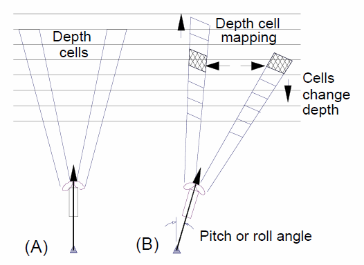
RDI ADCP data collected in Earth co-ordinates normally has had a depth cell mapping algorithm applied to align the depth cells to correct for tilt, while the other modes have not had it applied. Depth cell mapping is applied in post-processing in winADCP. Nortek's Storm / Surge post-processing software also applies bin-mapping when doing co-ordinate system rotations/transforms. (The term 'bin-mapping' is used by Nortek, RDI uses 'depth cell mapping'. We use 'bin-mapping' as it's the most common term in the literature.) Conversely, Nortek ADCP data collected in ENU co-ordinates has not had bin mapping applied. To apply bin-mapping, ENU data is converted back to Beam data, bin-mapping is applied and then converted back to ENU, doing any rotations as needed. The approach originated as described by Pulkkinen (1992). The Pulkkinen / RDI bin-mapping method is based on matching up the nearest vertical bin in each beam for each of the original range steps, then the radial velocities from those bins are used in the rotation to true Earth velocities. For compatibility with original VENUS ADCP data products, an alternative method is offered as a option as well, as described by Ott (2002). In that paper, the Ott method is shown to be an improvement over the discrete nearest vertical bin matching method. The Ott method uses a linear interpolation between the nearest vertical bins for each beam for each of the original range steps. The Ott method also interpolates over a small number of missing bins, otherwise missing data nullifies a greater extent of the data than it does in the nearest vertical bin method. The inner and outer most bins can end up with NaN values when there are less than 4 bins at the same vertical level, see the above graphic. This affects the nearest vertical bin method more so than the Ott method, and more bins are affected with increasing tilts.
Users are offered the option of 'None', 'Nearest vertical bin', or 'Linear interpolation (Ott method)'. When the data is in Earth co-ordinates, bin-mapping cannot be applied/modified. For RDI Earth data, the nearest vertical bin method has normally been applied, while Nortek Earth data does not have bin-mapping applied. In both cases, the users' preference may be overridden. The RDI manual indicates that pitch or roll values greater than 20 degrees are not possible and nominal processing has, in the past, applied NaN values when the pitch or roll exceeds that limit. However, we have found that RDI ADCPs can accurately report higher tilts. The limit is now set to 60 degrees for pitch/roll and at or above 90 degrees of average tilt, bin-mapping is overridden to the 'None' option.
Bin-mapping is not applied to the backscatter and intensity data. Instead, we offer a vertically corrected range in the mat file products and use this range for the plots when plotting against depth. For example, if the bin spacing is 1 m, but the tilt is 10 degrees, the vertical spacing is 0.98 m.
For advanced, interested users, here is the core code that does bin-mapping:
Three-Beam Solutions (For RDI ADCPs Only, Instr/Beam step #5)
In systems with four beams, the transformation from radial velocites to Earth co-ordinates velocities has redundant information; only three beams are needed to resolve currents in the three orthogonal directions, while the 4th beam effectively provides error estimation. In the case where exactly one bin out of of the four at any level is flagged and NaN'ed, then currents can still be calculated from the remaining three radial velocities, using the three-beam transformation solution. The screening steps that can flag the data 'NaN' prior to transformation include fish detection and correlation threshold, as well as any bin-mapping (particularly the RDI nearest vertical bin which can set many bins to NaN). The three-beam solution works by assigning the error velocity to be zero and then solving the transformation for the missing bin (for more details see Three Beam Solutions in adcp coordinate transformation_Jan08.pdf). With the missing data filled in, the normal transform from Beam to Instrument co-ordinate data is applied.
In cases where the data quality team has determined that an entire beam is bad, they can supply a device attribute specifying the bad beam number. That beam is then excluded in the processing from beam or instr co-ords and the values are filled in with the three-beam solution. Only the U,V,W results are affected, the raw velocity data as recorded by the instrument is presented without the exclusion. This forces the 3 beam option to on, regardless of the user input. The excluded beam number is mentioned in a comment on both the currents plot and intensity plots and in the processing comments in the mat files. This is currently only available for RDI ADCPs with 4 beams.
Here is the code for three-beam solutions and transform from Beam to Instrument (XYZ) co-ordinate data:
Screening
Correlation screening is the most widely applied and effective screening step, noted as step #3 in the Instr/Beam overall processing flow. It is also applied onboard RDI ADCPs when in Earth co-ordinate configuration, the value applied is available in the config structure.
Nortek ADCPs are generally three beam (so the three-beam solution option is not offered) and screening is not applied in the data products, except for a fixed 50% correlation screen on Nortek Signature55 data only, applied to match Nortek's Signature Viewer software.
RDI ADCPs screening steps also include a fish detection algorithm and screening, Instr/Beam step #4 in the overall process flow.
Once in Earth co-ordinates, the data can also be screened by the error velocity. Error velocity screening only applies to data with four valid beams (and non-zero error velocities). For further information on the screening steps, including algorithms, see adcp coordinate transformation_Jan08.pdf (RDI ADCPs only). This is step #9 in Instr/Beam and #2 in Earth data process flows.
Data Verification
As noted earlier, the ultimate requirement for the ADCP data products is that they replicate the results of the manufacturer's software. We test against the manufacturer's software to verify the data at every software release (regression testing). There are cases where this adherence is intentionally not true: if users choose any non-default option (or that says it's not the RDI default), the results will not match the default processing in the manufacturer's software, in particular, the Ott bin-mapping option is not available on winADCP at all. The testing suite includes manual and automated testing where the output of the manufacturer's software is compared to the data products and where data products are compared to the captured files from the previous release. The test suite is regularly updated for any new scenarios. Improvements in the test procedure are also made as needed. In addition to testing the software, there has been a significant effort to ensure that the metadata, in particular the heading metadata, is correct. These steps include careful measurement and documentation at deployment time, verifying and vetting ROV heading sensors, comparing data to nearby ADCPs, comparing results between various processing methods, and perhaps the best check is to compare the currents with the known/modelled tides. Contact us for information on the testing procedures and metadata verification.
A recent simplification in testing came about because of an improvement in the generation of RDI file data products, which we archive to speed up generation of subsequent products, MAT/NC files and plots. As of November 2015, RDI files with Beam or Instr co-ordinate data will incorporate the same heading/pitch/roll values as used for rotation and bin-mapping, that way, users and testers may load and process these files with RDI software, matching the values they can obtain from MAT and NC file products. For Earth co-ordinate data in RDI files, if we update the heading, we also need to rotate the East (u) and North (v) velocities as the new heading will be different from the internal compass heading (either fixed value, mobile position sensor or a magnetic declination is applied) on which the onboard Earth co-ordinate rotation was done. In this case, we don't update the pitch/roll as we cannot update the bin-mapping done for Earth data. Fortunately, the pitch/roll data is generally good and we do not yet have any examples where we do not use the internal pitch/roll data. Once the RDI files produced prior to November 2015 are re-generated, all RDI files will be made available in Data Search.
In all, the results from RDI winADCP, and Nortek software will match the processed data products. In addition, the original data, particularly the Beam co-ordinate data is always available in the RDI and Nortek raw binary files and as data.velocity (Nortek) and adcp.velocity (RDI) in the MAT files. The processingComments will completely describe the steps applied to produce the u,v,w processed velocities. In addition to the code snippets above, we are happy to supply more code, collaborate on that code, etc. We are interested in collaborating on QAQC processes, data verification, processing, analysis and research. Contact us if you have any questions.
MAT Files
MAT files (v7) can be opened using MathWorks MATLAB 7.0 or later. The file contains four structures: meta, adcp, config, and units. For short duration searches (less than one day) or short duration data returned, the files will be concatenated, otherwise, expect one file per RDI file. (RDI files can break in the middle of a day due to data quantity limits or configuration changes, otherwise there is one file per day. RDI files are used as a processing intermediary format.)

- deviceID: A unique identifier to represent the instrument within the Ocean Networks Canada data management and archiving system.
- creationDate:Date and time (using ISO8601 format) that the data product was produced. This is a valuable indicator for comparing to other revisions of the same data product.
- deviceName: A name given to the instrument.
- deviceCode: A unique string for the instrument which is used to generate data product filenames.
- deviceCategory: Device category to list under data search ('Echosounder').
- deviceCategoryCode: Code representing the device category. Used for accessing webservices, as described here: API / webservice documentation (log in to see this link).
- lat: Fixed value obtained at time of deployment. Will be NaN if mobile or if both site latitude and device offset are null. If mobile, sensor information will be available in mobilePositionSensor structure..
- lon: Fixed value obtained at time of deployment. Will be NaN if mobile or if both site longitude and device offset are null. If mobile, sensor information will be available in mobilePositionSensor structure.
- depth: Fixed value obtained at time of deployment. Will be NaN if mobile or if both site depth and device offset are null. If mobile, sensor information will be available in mobilePositionSensor structure.
- deviceHeading: Fixed value obtained at time of deployment. Will be NaN if mobile or if both site heading and device offset are null. If mobile, sensor information will be available in mobilePositionSensor structure.
- devicePitch: Fixed value obtained at time of deployment. Will be NaN if mobile or if both site pitch and device offset are null. If mobile, sensor information will be available in mobilePositionSensor structure.
- deviceRoll: Fixed value obtained at time of deployment. Will be NaN if mobile or if both site roll and device offset are null. If mobile, sensor information will be available in mobilePositionSensor structure.
- siteName: Name corresponding to its latitude, longitude, depth position.
- locationName: The node of the Ocean Networks Canada observatory. Each location contains many sites.
- stationCode: Code representing the station or site. Used for accessing webservices, as described here: API / webservice documentation (log in to see this link).
- dataQualityComments: In some cases, there are particular quality-related issues that are mentioned here.
- MobilePositionSensor: A structure with information about sensors that provide additional scalar data on positioning and attitude (latitude, longitidue, depth below sea surface, heading, pitch, yaw, etc).
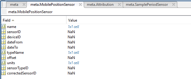
- name: A cell array of sensor names for mobile position sensors. If not a mobile device, this will be an empty cell string.
- sensorID: An array of unique identifiers of sensors that provide position data for mobile devices - this data may be used in this data product.
- deviceID: An array of unique identifiers of devices that provide position data for mobile devices - this data may be used in this data product.
- dateFrom: An array of datenums denoting the range of applicability of each mobile position sensor - this data may be used in this data product.
- dateTo: An array of datenums denoting the range of applicability of each mobile position sensor - this data may be used in this data product.
- typeName: A cell array of sensor names for mobile position sensors. If not a mobile device, this will be an empty cell string. One of: Latitude, Longitude, Depth, COMPASS_SENSOR, Pitch, Roll.
- offset: An array of offsets between the mobile position sensors' values and the position of the device (for instance, if cabled profiler has a depth sensor that is 1.2 m above the device, the offset will be -1.2m).
- sensorTypeID: An array of unique identifiers for the sensor type.
- correctedSensorID: An array of unique identifiers of sensors that provide corrected mobile positioning data. This is generally used for profiling deployments where the latency is corrected for: CTD casts primarily.
- deploymentDateFrom: The date of the deployment on which the data was acquired.
- deploymentDateTo: The date of the end of the deployment on which the data was acquired (will be NaN if still deployed).
- samplingPeriod: Sample period / data rating of the device in seconds, this is the sample period that controls the polling or reporting rate of the device (some parsed scalar sensors may report faster, some devices report in bursts) (may be omitted for some data products).
- samplingPeriodDateFrom: matlab datenum of the start of the corresponding sample period (may be omitted for some data products).
- samplingPeriodDateTo: matlab datenum of the end of the corresponding sample period (may be omitted for some data products).
- sampleSize: the number of readings per sample period, normally 1, except for instruments that report in bursts. Will be zero for intermittent devices (may be omitted for some data products).
- SamplePeriodSensor: A structure array with an entry for each scalar sensor on the device (even though this metadata is for complex data products that don't use scalar sensors).
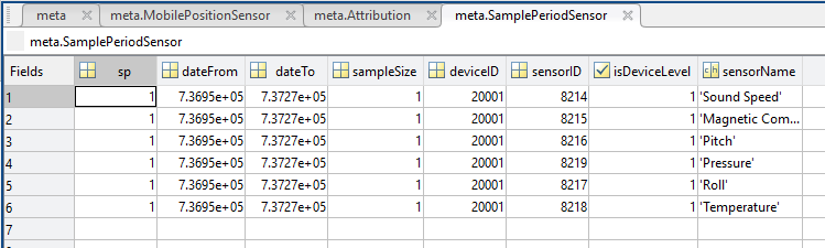
- sp: sample period in seconds (array), unless sensorid is NaN then this is the device sample period
- dateFrom: array of date from / start date (inclusive) for each sample period in MATLAB datenum format.
- dateTo: array of date to / end date (exclusive) for each sample period in MATLAB datenum format.
- sampleSize: the number of readings per sample period (array). Normally 1, except for instruments that report in bursts. Will be zero for intermittent devices.
- deviceID: array of unique identifiers of devices (should all be the same).
- sensorID: array of unique identifiers of sensors on this device.
- isDeviceLevel: flag (logical) that indicates, when true or 1, if the corresponding sample period/size is from the device-level information (i.e. applies to all sensors and the device driver's poll rate).
- sensorName: the name of the sensor for which the sample period/size applies (much more user friendly than a sensorID).
- citation: a char array containing the DOI citation text as it appears on the Dataset Landing Page. The citation text is formatted as follows: <Author(s) in alphabetical order>. <Publication Year>. <Title, consisting of Location Name (from searchTreeNodeName or siteName in ONC database) Deployed <Deployment Date (sitedevicedatefrom in ONC database)>. <Repository>. <Persistent Identifier, which is either a DOI URL or the queryPID (search_dtlid in ONC database)>. Accessed Date <query creation date (search.datecreated in ONC database)>
- Attribution: A structure array with information on any contributors, ordered by importance and date. If an organization has more than one role it will be collated. If there are gaps in the date ranges, they are filled in with the default Ocean Networks Canada citation. If the "Attribution Required?" field is set to "No" on the Network Console then the citation will not appear. Here are the fields:

- acknowledgement: the acknowledgement text, usually formatted as "<organizationName> (<organizationRole>)", except for when there are no attributions and the default is used (as shown above).
- startDate: datenum format
- endDate: datenum format
- organizationName
- organizationRole: comma separated list of roles
- roleComment: primarily for internal use, usually used to reference relevant parts of the data agreement (may not appear)
adcp: structure containing the ADCP data, having the following fields.
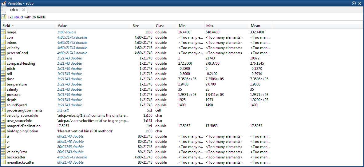
range: vector of distance to each bin centre. If bin mapping compensation for tilt is active, then the bins are moved so that ADCP.range is now the vertical range to the corrected bin centres (ADCP.range values are not changed by bin-mapping). See adcp.processingComments to see if bin mapping was applied. To calculate the depth of each velocity bin, use the following:
if strcmp(Config.orient, 'Up')binDepth = Meta.depth - ADCP.range;elsebinDepth = Meta.depth + ADCP.range;end- corr: 3D matrix, correlation time-series for each bin
- intens: 3D matrix, intensity time-series for each bin (also known as received signal strength intensity or RSSI, multiply by 0.45 dB/count to convert to a relative dB scale)
- velocity: 3D matrix, corresponds directly to output of instrument and so depends on configuration coordinate system
- percentGood: 3D matrix, percent good time-series for each bin
- ens: vector, ensemble number (replaced ensFirst for averaged products)
- ensFirst: vector of the first ensemble number in an ensemble average (averaged products only, replaces ens).
- compassHeading: vector, containing the EH values from the RDI files. This is either the fixed value from site and sitedevice headings (if not null), or values from an assigned true heading mobile position sensor. If neither, then it defaults to the magnetic compass heading data.
- pitch: vector, containing the EP values from the RDI files. This is either the fixed value from site and sitedevice headings (if not null), or values from an assigned true heading mobile position sensor. If neither, then it defaults to the onboard pitch sensor data.
- roll: vector, containing the ER values from the RDI files. This is either the fixed value from site and sitedevice headings (if not null), or values from an assigned true heading mobile position sensor. If neither, then it defaults to the onboard roll sensor data.
- time: vector, timestamp in datenum format (obtained from time the reading reached the shore station)
- temperature: vector, temperature time-series
- salinity: vector salinity time-series, (may contain constant values depending on device configuration)
- pressure: vector, pressure time-series. From RDI manual: "Contains the pressure of the water at the transducer head relative to one atmosphere (sea level). Output is in
decapascals". Converted to decibar. Can be a fixed value depending on configuration and hardware. In the binary RDI files and raw data streams, negative pressure values wrap - this isn't documented. In winADCP, negative values are truncated to zeroes, while in our data products and parsers we unwrap them to express the negative values (negative pressures should only occur in test or erroneous data). - depth: vector, depth of the device below the water surface as measured by the device for each ping. Can be set to a fixed value by the ED command / device attribute. For fixed deployments, this value is replaced in the RDI file by our code with the site depth plus offset, which is also reported as meta.depth. If not a fixed location deployment where the device is autonomous or mobile, this value is unaltered. It will vary with the tide and movement.
- soundSpeed: vector speed of sound time-series, (may contain constant values depending on device configuration)
- uMagnetic (optional): 2D matrix, East velocity relative to magnetic North
- vMagnetic (optional): 2D matrix, North velocity relative to magnetic North
- processingCommments: a string documenting all of the processing steps done to produce adcp.u/v/w. Use
char(adcp.processingComments)to print out the text. - processingOptions: a structure with the data product option set that was requested and what was actually done (not all options are available and maybe overriden at run time, this will be explained in the processingComments).
- velocity_sourceInfo: a string describing the source of data in adcp.velocity
- uvw_sourceInfo: a string describing the resulting final, rotated data in adcp.u/v/w
- magneticDeclination: value that can be applied to correct the compassHeading to true North
- binMappingOption: bin-mapping method applied as determined by the data product option chosen and data available.
- u: 2D matrix, East velocity relative to True North
- v: 2D matrix, North velocity relative to True North
- w: 2D matrix, Upward Velocity
- u_std, v_std, w_std: standard deviations for ensemble averaged u,v,w (averaged products only)
- u_count, v_count, w_count: the number of ensembles/pings that contributed to u,v,w (averaged products only). Differs from pingsPerEnsemble in that it accounts for filtered / NaN-ed data
- velocityError: 2D matrix, computed using RDI algorithm
- backscatter: 3D matrix based on received signal strength intensity (adcp.intensity), compensated for two-way spreading (20LogR) and absorption. Equation based on Gostiaux and van Haren ("Extracting Meaningful Information from Uncalibrated Backscattered Echo Intensity Data, Journal of Atomsheric and Oceanic Technology, 72, 943-949, 2010). The absorption computation follows Ainslie and Malcolm ("A simplified formula for viscous and chemical absorption in sea water", Journal of the Acoustical Society of America, 103(3), 1671-1672, 1998). Absorption coefficient based on mean depth, temperature and salinity in adcp structure.
- meanBackscatter: same as above, except averaged over the four beams to create a 2D matrix. Averaging is done by converting to standard intensity, averaging, then converting back to decibels.
config: structure containing ADCP configuration details, where some field names are appended with '_XX' to represent the corresponding configuration command (beneficial for experienced RDI ADCP users).

- fwVer: CPU firmware version
- fwRev: CPU firmware revision
- sysCfg: hardware configuration definition
- freq: frequency
- beamPattern: convex or concave
- orient: orientation (e.g.,'Up' indicates transducers are looking upward)
- beamAngle: beam angle
- janusCfg: description of Janus Configuration
- lagLength: time period between sound pulses
- nbeams: number of beams
- nbins_WN: number of bins
- npings_WP: number of pings per ensemble
- cellSize_WS: length per cell
- profilingMode: sigal processing mode
- corrThresh_WC: correlation threshold
- codeReps: code repetitions in transmit pulse
- percentGoodMin_WG: percent good threshold
- errVelThreshold_WE: error velocity threshold
- timePing_TP: time between pings within ensemble
- coord_EX: coordinate transformation processing parameters
- coordSys: coordinate system (evaluated from coord_EX)
- headingAlign_EA: correction factor for physical heading misalignment
- headingBias_EB: correction factor for electrical/magnetic heading bias
- heading_EH: manual setting of the heading from device attributes (not in RDI file, added after)
- sensorSrc_EZ: defines selected source of environmental sensor data
- sensorAvail: defines available sources of environmental sensor data
- bin1Dist: distance to the middle of the first depth cell
- transmitLength_WT: length of the transmit pulse
- falseTrgt_WA: false target threshold
- transmitLagDistance: distance between pulse repetitions
- cpuSN: CPU board SN
- sysBndwdth_WB: bandwidth setting (narrow or wide)
- sysPower_CQ: system power setting
- instSN: instrument serial number
- ensInterval: ensemble interval
- ambiguityVelocity_WV: radial ambiguity velocity (not in RDI, added after)
- soundAbsorptionCoefficient: sound absorption coefficient used for computing backscatter
units: structure containing unit of measure for fields in structures above. For instance, units.pressure='decibar'.

For details about the configuration parameters, refer to the manufacturer documentation (especially the WorkHorse Commands and Output Data Format manual).
Example: RDIADCP75WH3808_20101106T000225.mat
Oceans 3.0 API filter: extension=mat
NETCDF Files
NetCDF is a machine-independent data format offered by numerous institutions, particularly within the earth and ocean science communities. Additional resources are noted here. For short duration searches (less than one day) or short duration data returned, the files will be concatenated, otherwise, expect one file per RDI file. (RDI files can break in the middle of a day due to data quantity limits or configuration changes, otherwise there is one file per day. RDI files are used as a processing intermediary format.)
The RDI NetCDF file is extracted from the data contained in the above MAT file. The NetCDF file contains the following main variables: u, v, w, time, binmap_depth, where the binmap_depth variable here is distinct from the pressure sensor measurement in the MAT file (adcp.depth). When there is bin-mapping performed on the data, the binmap_depth is calculated as meta.depth - adcp.range; it is the approximate water depth at which the measurement bins are located. If bin-mapping is 'none', then the binmap_depth and the depth are equal. depth is calculated as meta.depth - adcp.backscatterVerticalRange, which is the range corrected for tilt. depth is used to plot the beam-averaged backscatter and any other beam-averaged values that are not bin-mapped. The structure and content of the netCDF file is very similar to that of the MAT file, including the variable naming. The RDI and Nortek netCDF files are intended to be very similar, even interchangeable with the same structure and definitions.
The NetCDF files are intended to be in compliance with the CF-1.7 standard. Depending on the compliance checker that is used the data may not meet this standard for the following reasons: The units dB are not defined, and the feature type of the data is not defined.
Oceans 3.0 API filter: extension=nc
Example: RDIADCP75WH17575_20130314T194500Z_20130502T164500Z-Ensemble900s_binMapNearest.nc
Discussion
To comment on this product, click Add Comment below.