Rotation of Velocities to East-North-Up Co-ordinate System
Velocity data acquired from RDI and Nortek ADCPs can take on several forms. The original, unaltered velocity data, read from the raw files is presented in the MAT file product as adcp.velocity (RDI) or data.velocity (Nortek). (Please note that the data structure names for RDI is adcp and for Nortek we use data, subsitute data for adcp when looking at Nortek data). Also in the MAT file product is the config struct that contains information on how the data was collected. Based on the configuration, the original data is processed to present the velocities relative to East-North-Up: this is the final data in the netCDF, MAT files and in the daily current plot PNG and PDF (see adcp.u, adcp.v, adcp.w in the MAT file and in the MAT file description below). u,v,w velocities are always relative to geographic North and local gravity (for Up).
In general, the aim of ADCP post-processing is to replicate the functionality in the manufacturer's post-processing software: RDI's winADCP and Nortek's Surge and Storm (which replaced ExploreP). RDI provides documentation on their rotations, see: ADCP Coordinate Transformation and the more general guide Acoustic Doppler Current Profiler: Principles of Operation - A Practical Primer (as a background only). Nortek's rotations are documented online, see: http://www.nortek-as.com/lib/forum-attachments/coordinate-transformation/view or the matlab code directly: post-2-71782-Xform.m. See RDI software support login for RDI software and http://www.nortek-as.com/en/support/software for Nortek software. We test against the manufacturers' software, but be aware that rotations are normally based on different data, as described below, as the manufacturers' software can only use the internal sensors available to it.
The coordinate system parameter determines the type of data that is acquired and how it is processed to produce u,v,w velocities. In the MAT file product, see config.coordSys. If the co-ordinate system is set to 'Beam', the original data contains the radial (along-beam) velocities for each of the 4 or 5 beams, otherwise the velocities are rotated to an orthogonal co-ordinate system: 'Instr' (RDI) or 'XYZ' (Nortek) means the original velocities have been rotated to a basis defined by horizontal plane of the instrument with an azimuth relative to the direction of beam 3, while 'Earth' is relative to the onboard magnetic compass or a fixed direction defined by config.heading_EH (RDI only). Our default setting is 'Beam' so that the most raw form of the data is collected. 'Ship' is not recognized/used. For RDI ADCPs, the co-ordinate system is either 'Earth' or 'Instr', the 4th row in the adcp.velocity matrix is the error velocity (the measurement error on the velocity at that bin and time).
RDI sensor source and sensor availability parameters determine if additional sensors are available to be used for rotation, such sensors include: magnetic compass, tilt sensor (for pitch and roll), depth, conductivity and temperature (the last three are used to determine the sound speed, however we normally fix that value, see config.soundspeed_EC). In the MAT file, see config.sensorSource_EZ and config.sensorAvail. If the magnetic compass is available, it is often used for Earth co-ordination rotation. The Nortek ADCPs always have compass and tilt sensors and prescribed sound speeds.
Magnetic compasses are not reliable when in close proximity to varying electromagnetic or magnetic fields (electric power cables or the steel instrument platform can cause the compass to be inaccurate). To improve the data, we normally supply a fixed heading from the site and device metadata. If the device is mobile, deployed on a mooring, cabled profiler or glider, a mobile position sensor is normally supplied. Here is an example of a mobile ADCP site: http://dmas.uvic.ca/Sites?siteId=100206 and here is an example of fixed site: http://dmas.uvic.ca/Sites?siteId=1000359. If the device is mobile and is attached to a device that can supply better orientation information, such as an optical gyro, the data processing code will make use of that device when its sensors are assigned to the heading/pitch/roll of the ADCP's site (we currently do not yet have an example of such a scenario). If the onboard magnetic compass is the only source of heading data, a correction is applied for magnetic declination. For fixed sites, the pitch and roll of the ADCP will be obtained from the site information. If fixed value or mobile pitch/roll sensors are not prescribed, then the onboard tilt sensors will be used, but will averaged over the dataset, since we can assume that the device is not mobile. If the devices' onboard pitch/roll sensor are assigned as mobile sensors for that site, then the pitch/roll data is not averaged.
Rotation of the input velocities to product East-North-Up velocities (u,v,w) is performed accounting for the incoming co-ordinate system, types and sources of the data. This is somewhat complicated, therefore, all of the processing steps are documented in the MAT files, see adcp.processingComments. As an example, here is a common scenario: raw data has been collected in the 'Earth' co-ordinate system defined by the onboard magnetic compass and pitch/roll senors, but the instrument is fixed with a known fixed heading, then difference between compass heading and the fixed is calculated and used to rotate the East and North velocities. In that case, adcp.processingComments would say:
Comments: adcp.velocity(1:3,:,:) contains the unaltered velocity data relative to the co-ordination system: Earth. acdp.velocity(4,:,:) is the RDI error velocity. adcp.u/v/w are processed velocities relative to true East/North/Up, respectively. Used a fixed heading of 228 degrees from meta data. Rotated adcp.u/v/w to true North from onboard Earth magnetic North, using a fixed or variable external source heading.
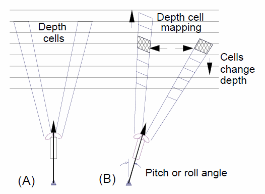
Correction for Tilt: Bin-mapping
In addition to coordinate system rotations, the orientation of the instrument affects the vertical range on which the measurement bins are spaced (depth cell and measurement bin are synonymous). If instrument is significantly tilted, the bins used to determine the velocities at each range will actually be a different water depths. Here is Figure 21 from Acoustic Doppler Current Profiler: Principles of Operation - A Practical Primer, notice in (B) that the highlighted depth cells are not the same as in (A):
RDI ADCP data collected in Earth co-ordinates has had depth cell mapping applied, while the other modes have not had it applied. Depth cell mapping is applied in post-processing in winADCP. Nortek's Storm / Surge post-processing software also applies bin-mapping when doing co-ordinate system rotations/transforms. (The term 'bin-mapping' is used by Nortek and in the literature, RDI uses 'depth cell mapping'.) Conversely, Nortek ADCP data collected in ENU co-ordinates has not had bin mapping applied. To apply it, ENU data is converted back to Beam data, bin-mapping is applied and then converted back to ENU, doing any rotations as needed. The approach originated as described by Pulkkinen (1992). The Pulkkinen / RDI bin-mapping method is based on matching up the nearest vertical bin in each beam for each of the original range steps, then the radial velocities from those bins are used in the rotation to true Earth velocities. For compatibility with original VENUS ADCP data products, an alternative method is offered as a option as well, as described by Ott (2002). In that paper, the linear interpolation method is shown to be an improvement over the discrete nearest vertical bin matching method. The Ott method uses a linear interpolation between the nearest vertical bins for each beam for each of the original range steps. The Ott method also smooths over a small number of missing bins, otherwise missing data nullifies a greater extent of the data than it does in the nearest vertical bin method.
As always, the original data is available from data.velocity (Nortek), adcp.velocity (RDI) in the mat files, while the processingComments describe the steps applied to produce the u,v,w processed velocities. We will supply source code on request as well. Contact us if you have any questions.